Documentation
How cadmark works
Architecture and workflow of the browser app: from the uploaded part through recognised features and stable identifiers to the assistant, previews and export.
Last updated: 11 October 2026 · describes the web version at beyware.com/app/
Overview
What: cadmark is a CAD application that runs in the browser. You upload a part (STEP, IGES, BREP or STL) or create a new one, cadmark recognises functional elements such as holes, countersinks, slots, pockets and ribs, gives each one a lasting identifier such as H3 or PK1 and shows dimensions straight from the CAD kernel. You change parameters, add sketches and operations, or describe the change to the assistant. Every change starts as a preview, can be applied or discarded and remains undoable. At the end you export STEP, STL or a technical drawing as PDF.
Who it is for: designers, engineers and makers who want to understand a part quickly and change it unambiguously, also together with an AI. Price, trial and account are on the product page.
Where it runs: on BEYWARE's server in Germany. The browser shows only the interface; geometry, recognition and export are computed on the server by the open-source kernel OpenCascade through CadQuery. Every account gets its own session with its own projects. Nothing is installed; a current browser on Windows, macOS or Linux is enough.
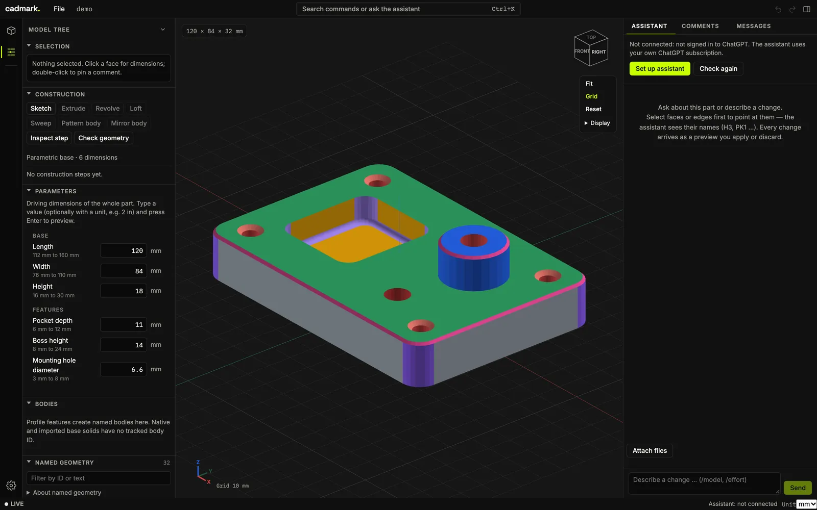
From model to feature
A CAD model consists of faces. cadmark groups these faces into named elements in a recognition cascade: two passes, nine stages. The first pass claims faces, the second only refines. Every face has exactly one owner; every element carries its reasoning and a quality score, so a decomposition is never a black box.
Recognised elements
- Holes (through and blind): coaxial cylinder groups, drill-point cones and centred floors form one hole, even when STEP splits them into halves. For blind holes the point angle is read.
- Counterbores and countersinks as the head of a hole; the countersink diameter comes from the exact boundary circles.
- Slots (through or blind) from pairs of partial cylinders with planar cheeks.
- Pockets, grooves, openings, steps.
- Ribs, bosses, pins, raised features.
- Chamfers, fillets, coves and functional planes (large planar faces).
Dimensions are read from the B-rep geometry, not estimated from the display mesh: diameter and depth of a hole, length × width of a slot from the axis distance of its partial cylinders, extent and normal of a plane, face area. Measuring between two elements (key I) also runs in the kernel: axis distance of two holes, normal distance of parallel planes, shortest distance, angle.
Standards matching for holes
Every hole diameter is checked against exact table values: clearance holes fine, medium and coarse after ISO 273, tap drills for coarse threads after ISO 2306/DIN 336, counterbores for ISO 4762 socket head cap screws after DIN 974-1 and 90-degree countersinks after ISO 10642/DIN 74, from M1.6 to M30. The tolerance is 0.005 mm so an inch part is not read as metric. A match then reads, for example, “M6 clearance medium (ISO 273), ISO 4762 socket head” or “M5 tap drill, likely thread M5x0.8”. A diameter alone does not prove intent, so cadmark always names the match as a reading and counts the alternatives.
Patterns
Several elements of the same type, size and orientation are grouped into patterns: linear rows, rectangular grids and bolt circles. Irregular sets are decomposed into equally spaced rows. The basis is the centroid of each element, which lies on the axis for every revolved feature, so a pattern does not depend on face order or STEP splitting. A pattern is what you mean by “4× M6 on 90 × 50” and what the assistant needs to change all four at once.
Stable identifiers
Internally every recognised feature carries a content hash as its id. A change of 0.01 mm already yields a new hash; comments, inspection dimensions and the assistant's own notes would lose their target on every parameter change. That is why every feature additionally gets a readable identifier made of a class prefix and a number:
| Prefix | Element | Prefix | Element |
|---|---|---|---|
| H | hole, blind hole | RB | rib |
| CB · CS | counterbore · countersink | BS · PN | boss · pin |
| SL | slot | CH · RD · FL | chamfer · fillet · cove |
| PK · GR | pocket · groove | ST · OP | step · opening |
| PL | functional plane | RF | raised feature |
Why H3 stays H3
Every model keeps a register of all identifiers it has ever issued. After a rebuild cadmark matches the newly recognised features against this register:
- Exact continuity. If a feature has the same content hash as before, the case is clear; no geometry is needed.
- Optimal assignment. For the rest cadmark solves an assignment problem per feature class (Hungarian method). The cost of a pairing is the displacement relative to the part size plus the change in dimensions and axis. A moved or enlarged hole keeps its name; a hole on the other side of the part does not.
- No guessing. An assignment counts only if it stays below a threshold and is clearly better than the runner-up. Symmetric twins stay unresolved: the feature gets a new number and a hint that it is probably the former H2.
Issued numbers are never reused. If H2 disappears, its entry stays in the register as “disappeared”, and the next new hole is H5, not H2. Old hashes become aliases of the current identifier, so a comment on a hole survives a resize. On the first build cadmark numbers in reading order, as a drawing would: H1, H2, H3 from top to bottom.
Below the identifier, individual faces get semantic references such as H3.wand0 (wall) or PK1.boden0 (floor): identifier, role and a deterministic index. Patterns carry the identifiers of their members. Identifiers, face references and old aliases can be used wherever you or the assistant address an element: in comments, measurements, inspection dimensions and tool calls.
The assistant
The assistant is a second operator with the same tools as you. It always works through your own account. Under Assistant settings you choose one of three options:
- ChatGPT: your own ChatGPT subscription. You sign in with a one-time code; cadmark runs the Codex CLI inside your own session. Data goes to OpenAI.
- Claude: your own Claude subscription (Pro or Max). You sign in via a link and a code inside the app; cadmark runs Claude Code inside your own session. Data goes to Anthropic.
- Ollama: your own Ollama server, reachable over https from the internet, or Ollama Cloud (ollama.com) with your own API key. The key is stored in your account settings on the BEYWARE server and never shown again. Data goes to the server you name, or to Ollama for Ollama Cloud.
You pick model and reasoning effort per project; /model and /effort in the chat switch quickly. BEYWARE has no AI contract of its own and bills no AI costs; there is no paid fallback. The BEYWARE server itself runs no AI model. The CAD features also work without AI.
What the assistant sees and can do
The assistant sees no pixels. It receives the part report: parameters with their limits, all features with identifier, dimensions, pattern and standards reading, operations, bodies, sketches and inspection dimensions. If you select faces or edges before asking, the selection travels along with its identifiers. Its tools, in groups:
- Read and query: part report, feature details, face and edge lists, geometry queries by type, diameter, depth, thread size, direction or proximity (
geometrie_abfragen), read source. - Change: set parameters; create, edit and remove operations (hole, pull, fillet, chamfer, linear and circular pattern, mirror); create and edit sketches; extrude, revolve, loft and sweep profiles; run custom CadQuery code on the finished body; replace source; create a new part from code.
- Name: propose, create and remove features; create and remove zones (“from where to where”).
- Check: measure exactly; create, edit and evaluate inspection dimensions; check identifier stability under parameter variation; check B-rep validity (
modell_pruefen); render model views as images (modell_ansicht); inspect earlier construction steps read-only. - Back channel: read, answer and create comments on the model; export the drawing.
Model images are rendered by cadmark from the actual CAD geometry; they serve the assistant as a check, never as a basis for measuring. If you attach a sketch (PNG, JPEG or WebP up to 5 MB), the image goes to the model as input; cadmark stores the original reference in the project and labels it a reference image, not a dimensionally accurate sketch.
Preview, apply, discard
Before every change the assistant reads model version and revision and sends both along. If the state has meanwhile become stale, cadmark rejects the call and the assistant has to read again. Parameter and operation tools return a receipt: whether applied, revision and model version before and after, changed parameters or operations, affected features and the measured bounding box and volume. The panel shows this receipt after reloading and after undo as well. A text answer from the assistant is not a receipt; only a tool can apply something.
Source changes are guarded further: the assistant reads code and a source token, checks the proposal as a preview (geometry, volume, feature losses, extent of the change) and only a second, explicit call with the same code and token applies it. Every source preview carries an id and a SHA-256 hash of the code; apply and discard must name both, otherwise the preview counts as replaced.
Undo and redo
Parameters, operations, sketches, source, feature names and zones share one history of up to 50 snapshots and the same revision (Ctrl+Z / Ctrl+Y). Undo restores the previously saved topology, including the intentional disappearance of a blind hole's floor when switching to a through hole. An undo at source level is checked geometrically again. Failed builds and lost features are never applied.
Limits of the assistant
The assistant can be wrong: misunderstand, choose an unsuitable tool or miss a check. cadmark forces it to produce receipts, not correctness. It must not work around parameter limits set in the model; for ambiguous faces, edges or bodies it should ask instead of guessing. Check every preview, and in particular dimensions, inspection dimensions and the drawing, before anything goes to manufacturing.
Construction
The model tree is the construction history. You and the assistant use the same operation ids, revisions, geometric validation and the same history.
Tools at the selection
Click a face or edge and the matching bar appears next to it: Pull (E), Hole (H), Fillet (F), Chamfer (C). Type a value, press Enter: the operation lands in the history (change value, disable, delete, hand to the assistant). This also works for imported STEP parts. If an operation cannot find its target after a rebuild, it is skipped and reported in red.
Parameters
The driving dimensions of a parametric part are in the model tree under Parameters, with the limits set by the part's author. Type a value (optionally with a unit, such as 2 in); Enter shows the preview. Operation values may be expressions over parameters so that a hole follows loch_d. Only numbers, parameter names, basic arithmetic and min, max, abs, round are evaluated; foreign code is rejected.
Sketches and profiles
- Sketch on a plane: rectangle, circle, ring, L-profile, flanged bushing section or closed polygon with driving dimensions. Dimensions of an earlier sketch are reachable as aliases, for example
O1_width. - Extrude as new body, add or cut, with a length, symmetric or “through all” in both directions.
- Revolve a closed profile by an angle.
- Loft as a ruled surface between two or more profiles on parallel planes (circles or convex polygons, no smooth interpolation).
- Sweep a circle or ring along a line or an arc up to 180° with optional tangent lines.
- Body patterns linear or circular with persistent copy ids; the count includes the original,
360/Ngives a full ring. Copies must stay disjoint. - Mirror a body on XY, XZ or YZ with an offset, or the whole part.
The sketch system is a directed construction graph, not a constraint solver; it claims no degrees of freedom it has not computed. Body identities follow exact construction provenance, never an index or a nearby face. A change that would lose a named element is rejected instead of silently redirected.
Checking
Inspection dimensions come from a measurement (“Keep as inspection dimension”) with a target as number or expression and a tolerance (default ±0.1 mm or ±0.5°). They appear in the model tree and as dimension chains on the stage: green when the dimension is right, red on deviation, grey when only observed. They are re-measured after every rebuild. Inspect step shows an earlier construction step read-only with the current dimensions; Check geometry rebuilds the saved B-rep independently and reports validity, topology and kernel diagnostics. The stability check varies parameters and sketch dimensions and reports which identifiers lose their faces.
Projects
Every project is its own folder with name, unit (mm or in), recognition setting and assistant choice. Templates when creating: empty part, hole plate, box, bushing, or a description and a reference image for the assistant. Duplicate creates a variant from the saved state with its own history. Delete removes a project permanently with all files, comments and exports.
Import & export
The browser has no access to the server's file system, so it sends the file itself (up to 50 MB). It lands in the project folder Imports; formats the importer cannot read directly are converted to STEP on upload, and the original is kept next to it.
| Format | Open | Export | Note |
|---|---|---|---|
| STEP | .step, .stp | yes | read directly; recommended exchange format |
| BREP | .brep, .brp | – | native OpenCascade format, read directly |
| IGES | .iges, .igs | – | converted to STEP on upload |
| STL | .stl | yes | mesh becomes faces; up to 60,000 triangles; export e.g. for 3D printing |
| – | yes | technical drawing with views, dimensions, hole table |
STL: what becomes exact and what does not
An STL mesh is sewn, closed into a solid and coplanar triangles are merged into real planar faces. Planar faces and dimensions between them are therefore exact. Curved faces stay facetted and are not recognised as holes. Meshes with more than 60,000 triangles are rejected with a request for STEP. Python part files are not accepted in the web version.
Technical drawing (PDF)
The drawing is derived from the exact B-rep through OpenCascade's hidden-line removal (HLR), not from the display mesh: circles stay circles, hidden edges are true hidden edges. The sheet follows the usual ISO conventions of a European workshop drawing:
- First-angle projection (ISO 128 / ISO 5456-2, method E): top view below the front view, view from the left to its right, isometric view in the free quadrant, symbol in the title block.
- Scale from the ISO 5455 series and the smallest sheet from A4 to A0 landscape that keeps the views legible; the isometric view takes the next smaller fitting scale.
- Lines after ISO 128, group 0.5: visible 0.5 mm, hidden, dimension and centre lines 0.25 mm; text height 2.5 mm after ISO 3098; centring marks after ISO 5457.
- Dimensions: overall dimensions once each (ISO 129-1), hole callouts such as “4× Ø5.2” in the view along the hole axis, centre marks, numbered for up to 60 holes.
- Hole table on sheet 2 with positions relative to the lower left front corner of the bounding box.
- Title block after ISO 7200 with title, number, material, revision, date, unit and general tolerance ISO 2768-m as the default.
The output is vector PDF. You set unit (mm or in), title and material on export; the assistant can trigger the drawing as well.
In the browser
You sign in at beyware.com/konto/ (German) and open beyware.com/app/. Before every request to the app the server checks the session with the account service; only accounts in the trial or with an active subscription get through.
- Your own workspace per account. Every account gets its own cadmark server process with its own projects, outputs and its own assistant sign-in. Nobody sees anyone else's work. The process starts on the first request and stops after 20 minutes without requests; your projects stay saved.
- Your own session. Every account gets its own CAD session, without a queue or seat limit. After 20 minutes without requests it is stopped; your projects stay saved.
- Data in Germany. Projects and uploads are stored on the server managed by BEYWARE in Germany, separated per account. If you delete your account, the workspace with all files is removed. Details in the privacy policy and the terms of use (German).
- No installation. A current browser on Windows, macOS or Linux is enough. Up to 760 pixels wide the interface switches to a compact layout with bottom navigation and tool sheets; a desktop or laptop screen is recommended.
- Account. The first 7 days of an account are free; after that the subscription runs monthly. You can cancel in your account, effective at the end of the current period, or through the cancellation form without signing in.
Limits & responsibility
- The face key is geometry-based: it survives re-meshing and reordering but not a change of geometry. That is what identifiers and the fallback anchors of comments (face key → identifier → point) are for.
- Imported STEP and BREP parts have no reconstructed construction history and no design intent. Their identifiers hang on the existing geometry. Sketches and operations added later are parametric.
- Whether a hole is through or blind cannot be told from the cylinder face alone; “depth” is measured along the axis. The extent of a plane is its bounding rectangle; merged faces no longer deliver the nominal dimensions of the original feature.
- The stability check takes finite samples. It uncovers fragile references but does not guarantee stability under all possible changes.
- Kernel validity does not mean correct dimensions, absence of overlap between bodies or manufacturability. An image proves neither dimensions nor hidden geometry.
- Loft and sweep deliberately cover a small envelope (see Construction). Hidden dimensions cannot be inferred from a single photo.
- The assistant can be wrong. No availability of the service is guaranteed; export important states as STEP.
cadmark is a tool. You are responsible for the professional check of the parts, dimensions and drawings it produces, for example before manufacturing.
FAQ
Does H3 really stay H3 when I change the part?
For supported changes, yes. After every rebuild cadmark matches the recognised features against the register of issued identifiers: first by exact continuity, then by an optimal assignment over position, size and axis. If H3 moves or grows, it stays H3. Only when two symmetric candidates fit equally well does cadmark prefer a new number and say so. Issued numbers are never reused.
Can the assistant change my model without asking?
No. Every change the assistant triggers through its tools arrives as a preview with a receipt (revision before and after, affected features, measured bounding box and volume). It is saved only when you apply it; discarding leaves the saved state untouched. Applied changes can still be undone.
What goes to the AI provider when I use the assistant?
Your requests, the answers of the cadmark tools (reports with identifiers and dimensions, measurements, check results), model images that cadmark renders from the exact geometry when asked, and sketch images you attach yourself. All of this goes only to the provider you chose: OpenAI for ChatGPT, Anthropic for Claude, and for Ollama the server you name (Ollama for Ollama Cloud). That provider's terms apply; cadmark has no AI contract of its own and no paid fallback.
Why does cadmark not recognise holes in my STL file?
An STL mesh contains only triangles. cadmark sews it into a solid, merges coplanar triangles into real planar faces and writes a STEP file. Planar faces and dimensions between them are exact; curved faces stay facetted and are not recognised as holes. If you have the original as STEP, upload that instead.
Why can I not edit the dimensions of an imported STEP file directly?
A STEP file contains only the result, not the construction history. cadmark does not reconstruct source parameters and therefore shows no seemingly editable dimensions. You can add operations to the imported part (hole, pull, fillet, chamfer) and create new sketches with their own drivers; those are parametric and covered by the stability check.
Which standards does cadmark match holes against?
Clearance holes fine, medium and coarse after ISO 273, tap drills for coarse threads after ISO 2306/DIN 336, counterbores for ISO 4762 socket head cap screws after DIN 974-1 and 90-degree countersinks after ISO 10642/DIN 74, for M1.6 to M30. The tolerance is 0.005 mm so that inch parts are not read as metric. A match is a reading, not proof of intent, and is named exactly that.
Do I have to wait for a free seat?
No. Every account gets its own CAD session on first use, without a queue. After 20 minutes without requests it is stopped and starts again on your next visit. Your projects stay saved.
Does cadmark work without AI?
Yes. Upload, recognition, identifiers, measuring, inspection dimensions, sketches, operations, parameters, previews, undo and export all work without the assistant. The assistant is an additional operator using the same tools.
Missing a question? Write to kontakt@beyware.com. Price and trial: cadmark product page.